Drawing Disciplines Supported:
Technical Documents and Drawings:
- Block Diagrams

- Audio, Video, Control, Functionals
- Rack Elevations
- Equipment Lists
- Console Layouts
- Run Sheets
- AV Router Layouts
- Master Control
- Sub Control Rooms
- Data Router Layouts
- Network Transmission
- Compression Systems
- Satellite HPA Room
- Up/Downlink
- Non Linear Editing Systems
- Intercom System Drawings
- Data Centers
- Schematics
- Project Manuals
Architectural Drawings:
- Floor Plans
- Site Plans
- Reflected Ceiling Plans

- Raised Floor Plans
- Acoustical Details
Electrical Drawings:
- Technical Floor Plans
- Electrical One Lines
- Tech Power Layouts
- Cable Tray Layout
- Data/Telephone
- Network Connectivity
- Tech Raised Floor Plans
- Tech Ceiling Plans
- Power Distribution Layouts
- Electrical Panel Diagrams
- Cable Drawings
- Circuit Breaker Diagrams
- Telecommunication Distribution Diagrams
- Grounding Plan
- Theatrical Lighting Plan
- Lighting Plan
HVAC Drawings:
- Studio HVAC Analysis
- HVAC Schematics
- HVAC RCP coordinated outlet plans
Supplemental Infrastructure Drawings:
- Fire Alarm Schematics
- Security Camera
- Security System Plans
3D Rendering:
We can provide AutoCAD 3D modeling stretched up from plan view to show Wire frame and Hidden Line in 3D perspectives.
CAD Conversions:
We will convert your PDF files to AutoCAD files with the use of conversion software. We will then retouch the resultant conversion with in AutoCAD, fixing the line work text and organizing the layers.
Technical Drawing Types:
Our drawing training and experience is in AutoCAD and for that reason prefer to use our licensed versions. We have on client request used otherI however
Standard Drawings: are created using traditional AutoCAD features, where drawing objects the connecting lines forming the schematic and text information are keyed in a flat plane much like sketching on a sheet of paper. The standard drawing in its basic form does not contain attributes and stores its objects and text information in a composite AutoCAD file. The wiring (text) information with-in the CAD file is not practically extractable to an external file.
Smart Drawings: have a similar appearance to the standard drawing however are developed using pre-defined blocks with embedded attribute fields. The equipment descriptions and wiring information are keyed into attached block attributes using their pop-up tags for entry. The attribute information and schematic line work forms the composited graphics file and provides viewing of all objects. The attribute information can be later extracted to an external file such as Excel. The attribute method of storing wiring information provides a single entry point, increasing accuracy and extraction to run sheets, equipment lists etc.
Smart Drawings Notes: Creating drawings with attributes have many advantages, especially when you take advantage of extracting wiring information from the CAD(s) to create, Jackfield Labels, Run Sheets, Router Layouts, etc. The accuracy between documents increases dramatically, and the all too common future editing of in house wiring changes is much easier because the data is keyed in and stored in one place (the CAD) and through a macro can be exported to many pre-made templates instead of creating individual spreadsheets for each then rendering and updating each one.
AutoCAD Design and Drafting:
Starting from Scratch: We would be pleased to develop your hand drawn sketches, markups, or an equipment list into a AutoCAD drawing using either your provided CAD Drawing Specification or one of the default setups available in our library.
Updates: If you have an as-built [DWG] CAD file, with either a hand mark-up or a [DWF] CAD red line, we will match into your CAD file, capturing the modifications found in your provided update detail.
Before editing: with your approval, we will review your as built drawings’ for: line type, color, scale and layer discipline verifying against your engineering specification, making adjustments if needed to bring the default drawing into standard before we begin editing. This to ensure the final output is a fully coordinated CAD file.
Revision Clouds, Names and Notes: We will highlight all changes made to drawings using revision clouds making it easy to view the updates. The clouds will be placed in their own layer. We will also add revision notes keyed into the Title Block and rename the CAD file according to your standards or add a dash number creating a unique file saved in an AutoCAD version of your choice.
Technical Drawing Types:
Standard Drawings: are created using traditional AutoCAD features, where drawing objects the connecting lines forming the schematic and text information are keyed in a flat plane much like sketching on a sheet of paper. The standard drawing in its basic form does not contain attributes and stores its objects and text information in a composite graphical file.
Smart Drawings: have a similar appearance to the standard drawing however are developed using pre-defined blocks with embedded attribute fields. The equipment descriptions and wiring information are keyed into attached block attributes using their pop up tags for entry. The attribute information appearing as text and schematic line work forms the composited graphics file providing full viewing of all the objects. The attribute information can be later extracted and to an external file such as Excel. The attribute method of storing wiring information provides a single entry point, increasing accuracy and extraction to run sheets, equipment lists etc.
Smart Drawings Types:
- Block Diagrams
- Audio, Video, Control Functionals
- Rack Elevations
- Console Layouts
- Electrical One Line
- Electrical Panel Board
Note: Examples of extracted spreadsheet files can be viewed in the Gallery.
Smart drawing Extraction Types:

- Run Sheets
- DA Lists
- AV, SDI, and Data Jack fields
- AV Router Layouts
- Data Router Layouts
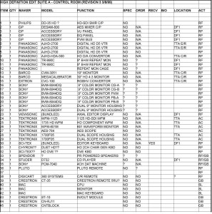
- Equipment Lists
- Custom
Model Space and Paper Space:
Model Space:
Model Space offers a wide range of flexibility, especially advantageous for architectural drawing presentation. In model space, you can draw all objects at 1:1 scale. Then you can present them in Paper Space by opening scaled view ports.
Paper Space:
In paper space, you can create multiple tabs, you may place your title block, create a layout using one or multiple view ports to highlight objects, show dimensions, details and isometric views. When you open a paper space tab you can configure the printer type and sheet size for your plot choice. Then you cut holes in the virtual paper as a view port allowing you to expose the model space objects and controlling the scale at which you see them.
One of my preferences in paper space is to create several tabs, then under each tab create plot device and paper size for each desired for a project. As an example [Tab-1] Plot 18×24, [Tab-2] Plot 11X17, [Tab-3] PDF 11X17.
Our Engineering Specifications:
Layer colors:
- 0 White

- Approval White
- Attext Red
- Border Magenta
- Cable White
- Cable Numbers Green
- Connectors White
- Defpoints White
- Equip Dark Gold
- Frame White
- Jack Numbers White
- Leader-Ins White
- Leader- Outs White
- Numbers White
- Schematic White
- Text Cyan
- Text (in Blocks) 140
- Title Block Info White
- Wires White
Plotting Sizes Available:
In House:
- A 8.5×11
- B 11×17
- C 18×24
- D 24×36
Custom Plotting Sizes available on request.